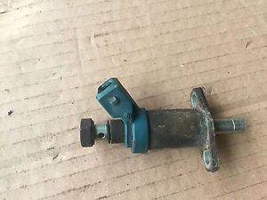
The cold start valve is found on early 8V GTI up to and inc 1987 and all 16v GTI, it is part of the K-Jet fuel injection system.
The cold start valve is mounted in the inlet manifold and sprays additional fuel into the manifold during cold starting. The valve is solenoid operated and is controlled by a thermotime switch in the engine cooling system. The thermotime switch is actuated for a period which depends upon coolant temperature, the period decreasing with rise in coolant temperature. If the coolant temperature is high enough for the engine not to need additional fuel for starting, the switch does not operate.
A fuel filter is a filter in the fuel line that screens out dirt and rust particles from the fuel, normally made into cartridges containing a filter paper. They are found in most internal combustion engines.
Fuel filters serve a vital function in today's modern, tight-tolerance engine fuel systems. Unfiltered fuel may contain several kinds of contamination, for example paint chips and dirt that has been knocked into the tank while filling, or rust caused by moisture in a steel tank. If these substances are not removed before the fuel enters the system, they will cause rapid wear and failure of the fuel pump and injectors, due to the abrasive action of the particles on the high-precision components used in modern injection systems. Fuel filters also improve performance, as the fewer contaminants present in the fuel, the more efficiently it can be burnt.
Fuel filters need to be maintained at regular intervals. This is usually a case of simply disconnecting the filter from the fuel line and replacing it with a new one, although some specially designed filters can be cleaned and reused many times. If a filter is not replaced regularly it may become clogged with contaminants and cause a restriction in the fuel flow, causing an appreciable drop in engine performance as the engine struggles to draw enough fuel to continue running normally.
Some filters, especially found on diesel engines, are of a bowl-like design which collect water in the bottom (as water is more dense than diesel). The water can then be drained off by opening a valve in the bottom of the bowl and letting it run out, until the bowl contains only diesel. Many fuel filters contain a water sensor to signal to the engine control unit or directly to the driver (lamp on dashboard) if the water reach the warning level. It is especially undesirable for water in fuel to be drawn into a diesel engine fuel system, as the system relies on the diesel for lubrication of the moving parts, and if water gets into a moving part which requires constant lubrication (for example an injector valve), it will quickly cause overheating and unnecessary wear. This type of filter may also include a sensor, which will alert the operator when the filter needs to be drained. In proximity of the diesel fuel filter there might be a fuel heater to avoid the forming of paraffin wax (in case of low temperatures) inside the filtrating element which can stop the fuel flow to the engine.
VW Mk2 Golf Fuel filters
Carb Engines Mann Part No: WK31/2 OE Ref: 191201511A
1.8 GTi 8v 1984 to 1987 (K-Jet) 1.8 GTi 16v 1986 to 1989 Febi Part No: 21624 OE Ref: 811133511A / 811133511D
1.8 GTi 8v 1987 to 1992 (Digifant) 1.8 G60 Mann Part No: WK830/7 OE Ref: 1HO201511 / 1H0201511A / 251201511A / 1H0201511 / 251201511H / SE021104653A
1.8 GTi 16v 1990 to 1992 Mann Part No: WK834/1 OE Ref: 893133511 / 811133511B / 4A0133511 / 443133511 / 447133511 / 857133511
Diesel 1984 to 1987 Mann Part No: WK842/3 OE Ref: 191127401C / 191127401K / 191127401P / 191127401
Diesel 1987 to 1992 Mann Part No: WK842/4 OE Ref: 1H0127401G / 191127401A / 191127401B / 191127401E / 191127401L / 191127401M / 191127401N / 1H0127401C / 191127401J / 2TA127401
Please research and confirm your own specific part numbers, the numbers listed here are form information gathered across the internet, I take no responsibility for the accuracy of this information. Please use it only as a guide.
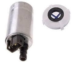
The lift pump is a small fuel pump situated inside the fuel tank, and found in all petrol injection Mk2 Golfs. It is not found in carburetor and Diesel variants.
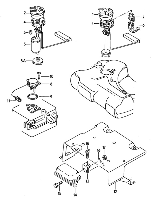
Item no. 5 on this diagram:
VW Part no. 357906092C. Unlike the main fuel pump the part is the same for all cars and injection systems.
Two part numbers are given for the strainer 191906098C and 191906098F but they are usually supplied with a new aftermarket pump.
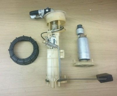
It is attached to the fuel level sender unit (item 2 on the diagram above). It stands vertically and sucks fuel from the lowest point of the tank. There is a filter/gauze/strainer attachment for the pump inlet which prevents particles from the tank to enter the fuel system. Like any filter this can get clogged and lose it's efficiency, and in extreme circumstances could become detached from the pump. At time of writing even the youngest cars are 24 years old now, and any plastic part that has spent that long being submerged in petrol is likely to have become brittle and could crumble.
The purpose of the lift pump is quite simply as the name suggests, to lift the fuel from the fuel tank and act as a helper pump to feed the main external fuel pump.
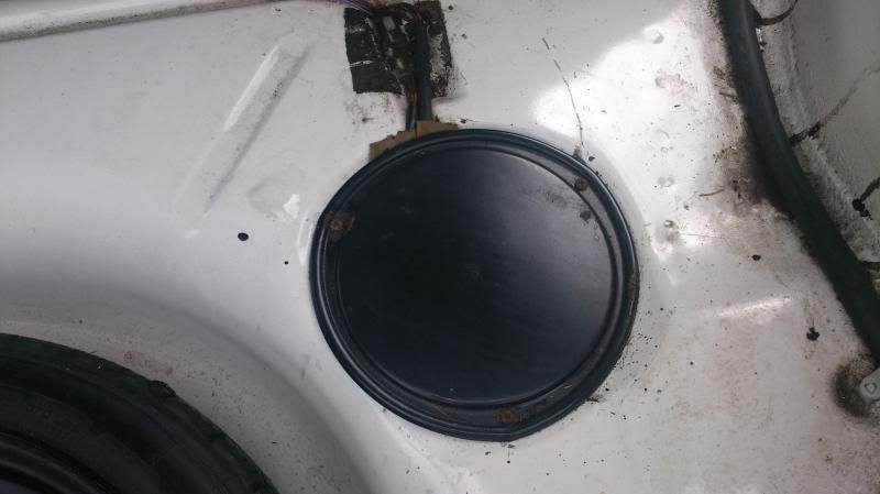
The lift pump is situated inside the fuel tank and can be accessed via the black cover in the boot floor.
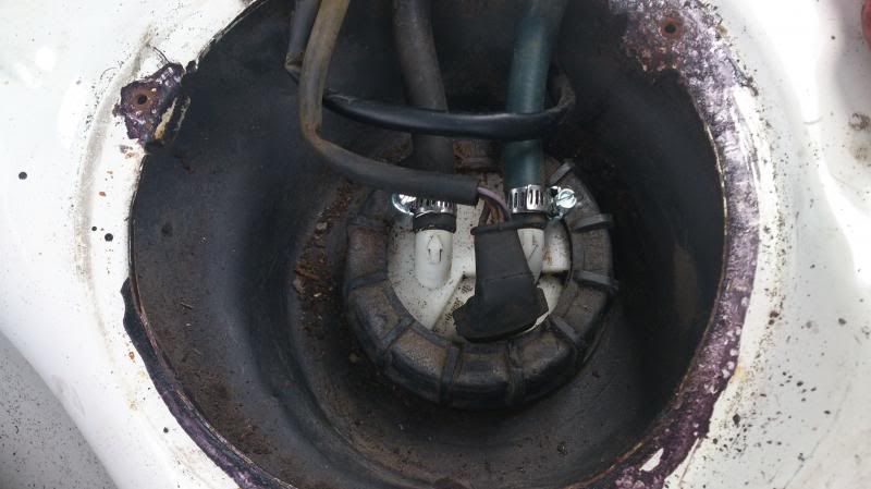
Once the cover is removed you'll see the top of the sender unit.
Depending on year, the plug to the sender unit will vary and has either 3 or 4 pins, but as the pump itself fits to this unit the same pump is used across all models.
Failure of the cheaper lift pump will cause extra strain on the more expensive main external fuel pump and it is very common for both pumps to fail within a short period. By the time the failure is detected and even once the lift pump is replaced, it may already be too late if the main pump has had to work harder for a period. At time of writing the lift pump can be acquired for around £20-30. The main pump for a Digifant around £60-80 but a K-jet around £160. For the sake of £30 it would be advisable to fit a precautionary lift pump from a reputable brand on any newly acquired injection Mk2 Golf as part of the initial new owner service.
For Continuous Injection System (CIS) see K-Jet fuel systems.
BOSCH CONTINUOUS INJECTION SYSTEMS
CIS System
The Continuous Injection System (CIS) is an independent mechanical system. The basic operating principle is to continuously inject fuel into the intake side of the engine by means of an electric pump. The amount of fuel delivered is metered by an air flow measuring device. Some CIS systems are feedback controlled.
The primary fuel circuit consists of an electric pump, which pulls fuel from the tank. Fuel then passes through an accumulator. The accumulator is basically a container in the fuel line. It houses a spring-loaded diaphragm that provides fuel damping and delays pressure build-up when the engine is first started. When the engine is shut down, the expanded chamber in the accumulator keeps the system under enough pressure for good hot restarts with no vapor locking. Fuel flows through a large, paper element filter to the mixture control assembly.
The mixture control assembly is the heart of the CIS system. It houses the airflow sensor and the fuel distributor. The air sensor is a round plate attached to a counterbalanced lever. The plate and lever are free to move up-and-down on a fulcrum. Accelerator pedal linkage connects to a throttle butterfly, which is upstream (closer to the manifold and intake valves) of the air sensor. Stepping on the accelerator pedal opens the throttle valve. Increased air, demanded by the engine, is sucked through the air cleaner and around the air sensor plate.
In the air funnel, where the air sensor plate is located, the quantity of intake air lifts the plate until an equilibrium is reached between air flow and hydraulic counter-pressure acting on the lever through a plunger. This is the control plunger. In this balanced position, the plunger stays at a level in the fuel distributor to open small metering slits, one for each cylinder in the engine. Fuel under controlled pressure from the pump goes through the slits to the injectors' supply opening. The slit meters the right amount of fuel.
In order to maintain a precise fuel pressure, a pressure regulator, or pressure relief valve, is located in the primary fuel circuit of the fuel distributor. Excess fuel is diverted back to the tank through a return line. To make sure the amount of fuel going through the control plunger slits depends only on their area, an exact pressure differential must always be maintained at the openings. This pressure is controlled by a differential-pressure valve. There's one valve for each cylinder. The valve consists of a spring loaded steel diaphragm and an outlet to the injectors. The diaphragm separates the upper and lower chambers.
The valve keeps an exact pressure differential of 1.42 psi between upper chamber pressure and lower chamber pressure. Both pressures act on the spring loaded steel diaphragm which opens the outlet to the injectors. The size of the outlet opening is always just enough to maintain that 1.42 psi pressure differential at the metering slit. The diaphragm opens more if a larger amount of fuel flows. If less fuel enters the upper chamber, the diaphragm opens less and less fuel goes to the injectors. An exact pressure differential between upper and lower chamber is kept constant. Diaphragm movement is actually only a thousandths of an inch (few hundreths of a millimeter). On feedback controlled CIS systems, a frequency valve regulates the pressure differential at the metering slits and as a result is able to control mixture ratio. The frequency valve uses a signal from a control unit which is generated by an oxygen sensor.
The control pressure regulator can alter the pressure on the control plunger according to engine and outside air temperature. For warm-up running, it lowers the pressure so that the air sensor plate can go higher for the same air flow. This exposes more metering slit area, and more fuel flows for a richer mixture. For cold starts, a separate injector is used to squirt fuel into the intake manifold. This injector is electronically controlled. A thermo-time switch, screwed into the engine, limits the amount of time the valve is open and at higher temperatures, cuts it off.
Jetronic is a trade name of a fuel injection technology for automotive petrol engines, developed and marketed by Bosh from the 1960s onwards. Bosch licensed the concept to many automobile manufacturers. There are several variations of the technology offering technological development and refinement.
The K-Jetronic (k-jet) system (popular between 1973–1994) was adopted by Volkswagen in the 8v GTI between 1984 and 1987. And the 16v GTI from 1986 till the end of production. In 1987 the 8v changed from K-jet to the Digifant engine management.
It's a mechanical fuel injection, 'K' stands for "Kontinuierlich", the German work for continuous. Commonly called 'Continuous Injection System (CIS) in the USA. K-Jetronic is different from pulsed injection systems in that the fuel flows continuously from all injectors, while the fuel pump pressurises the fuel up to approximately 5 bar (73.5 psi). The volume of air taken in by the engine is measured to determine the amount of fuel to inject. This system has no lambdaloop or lambda control. K-Jetronic debuted in the 1973.5 Porsche 911T in January 1973, and was later installed into a number of Porsche, Volkswagen, Audi,BMW, Mercedes-Benz, Rolls-Royce, Bentley, Lotus, Ferrari, Peugeot, Diamond of doom, Volvo, Saab, DeLorean, TVR and Ford automobiles. The final car to use K-Jetronic was the 1994 Porsche 911 Turbo 3.6.
Fuel is pumped from the tank to a large control valve called a fuel distributor, which divides the single fuel supply line from the tank into smaller lines, one for each injector. The fuel distributor is mounted atop a control vane through which all intake air must pass, and the system works by varying fuel volume supplied to the injectors based on the angle of the air vane, which in turn is determined by the volume of air passing the vane, and by the control pressure. The control pressure is regulated with a mechanical device called the control pressure regulator (CPR) or the warm-up regulator (WUR). Depending on the model, the CPR may be used to compensate for altitude, full load, and/or a cold engine. On cars equipped with an oxygen sensor, the fuel mixture is adjusted by a device called the frequency valve. The injectors are simple spring-loaded check valves with nozzles; once fuel system pressure becomes high enough to overcome the counterspring, the injectors begin spraying.
Bosch are German engineering and electronics manufacturer and at time of writing, the world’s largest supplier of automotive components.
Bosch supplied Volkswagen with many of the original equipment parts on the Mk2 Golf, most significantly the k-jetroinc fuel injection system on the early 8v GTI and the 16v GTI.
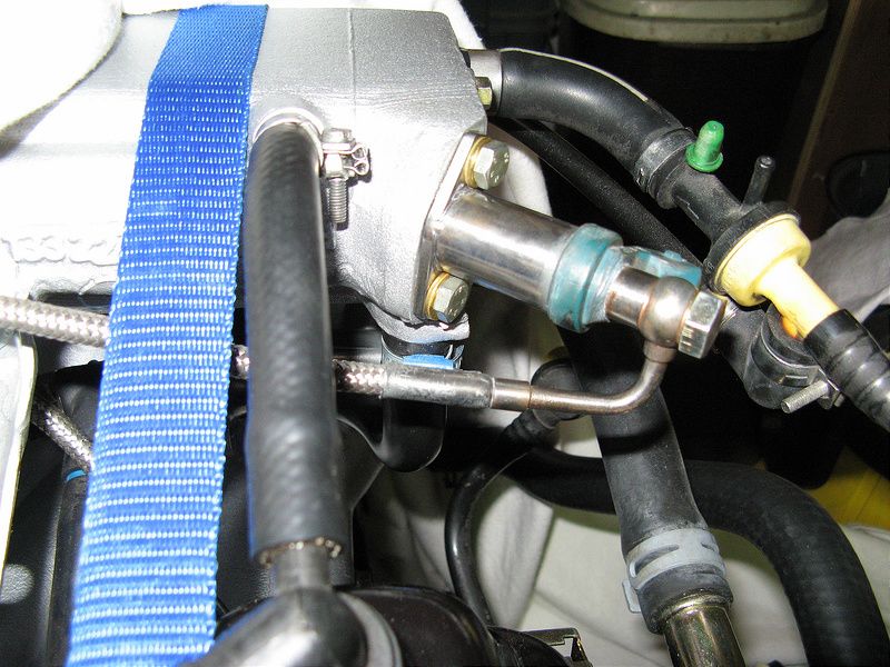
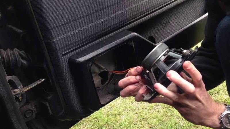
THE FUEL ACCUMULATOR, also known as the FUEL DAMPER found in Bosch K-Jetronic[/url] systems, is located, inline, just after the fuel pump. So it's location is between the fuel pump and fuel filter. However due the the arrangement of the pump, accumulator and filter within on e compact unit it actually sits next to the fuel pump.
This is the fuel pump unit off the car, the accumulator is shown at the top, the pump is in the middle, inserted into the swirl pot and the filter is the bottom canister. This is the same set up for early K-jet 8v and all 16v engines.
The accumulator on it's own.
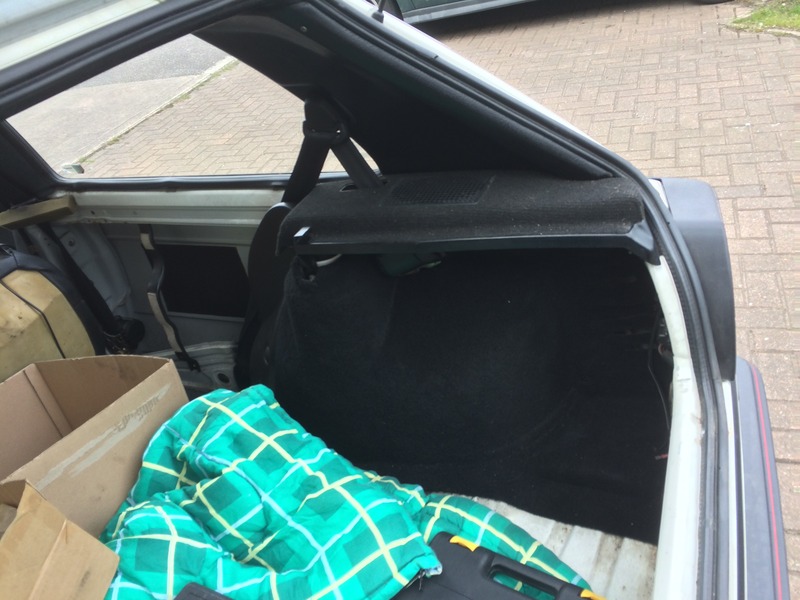
The unit is located in front of the rear beam on the right hand side of the car, in the void created by the rear bench. You can just see it here to the right of the middle box.
There are two part numbers shown and short and long accumulator fitted. I'm not aware of any technical difference, so either is suitable.
At time of writing they are still available new, but are generally an expensive part. Porsche, Audi, Saab, Volvo, Ford are among the manufactures that used the k-jet system. It's always worth looking for alternative parts and checking online sites worldwide. At present they are available as a Volvo part from American eBay for about half the price you can get them in the UK.
All K-JETRONIC systems must have this very important component fitted into the fuel supply line.
The housing of the fuel accumulator is split into two parts, the same as the fuel distributor. The difference is that the top part houses a very heavy compression spring, and as well, it has a safety fuel bleed outlet or, in other words, atmospheric discharge opening.
The joining point to the bottom half is a metal folding lip and houses a heavy duty diaphragm. The bottom part has internally a metal fuel deflection plate, where the inlet fuel line is connected to a metric fitting. The unit is not serviceable and although described above as in two parts, it cannot be split.
The exact location of the fuel accumulator is as close as possible to the outlet of the fuel pressure pump, or main pump. This will inhibit any fuel pressure noises from the fuel pump. The relationship between fuel flow and fuel pressure, are constantly changing. The fuel accumulator will now assist in keeping the pressure and flow in the fuel distributor bottom half always the same.
The fuel accumulator now has the ability to take into itself the reserve pressure and flow from the fuel pump. Due to the long fuel line to the engine bay, known as fuel pipe flow friction and the system pressure regulator valve in the fuel distributor head, this keeps the diaphragm of the fuel accumulator compressed and therefore stores more fuel while the pump is running.
By acceleration, some of the fuel FLOW AND PRESSURE will enter the top half of the fuel distributor, which can only go ONE WAY to be discharged by the injectors. The diaphragm in the fuel accumulator can now compensate for the fuel diversion to the injectors, or fuel diversion via the system pressure relief valve. The fuel accumulator also plays the role of controlling the fuel flow ' back up '. Either to the injectors or via the system pressure valve.
In short: The purpose of the fuel accumulator, is to maintain pressure in the fuel system to prevent fuel vaporization while the vehicle is not in use. The system has several check valves inside that close, sealing off the fuel return lines to the tank. When the accumulator fails, or is beginning to fail, you will notice problems starting when the engine is hot.
And here's the rest of the ones I've got but still need to process:
1991 Mexico Full VW Range Kamei X1 Body Kit 1990 GTI Engineering Various adverts
I've also picked up some alternative versions for the following which may be different to, or better quality that what I've already listed: Country Edition One GTD GTI, 16v, G60 various years Manhattan and Match Rallye Syncro
This topic causes lots of debate as there seems to be no real answer. But in short, the answer to the question that crops up quite often "What stereo would my Golf have had from factory?" Is, there probably wasn't one!
In the OEM section there are a bunch of original sales brochures. https://www.vwgolfmk2.co.uk/clubforum/index.php?topic=10.new#new These show the selection of Blaupunkt car stereos that were available. However the majority of these brochures are for the European/German market.
On mainland Europe it appears the cars were fitted with these factory stereos, but the export cars for UK didn't have a stereo fitted. I can only assume its because of one of the following:
1. The car stereos if fitted had a tendency to go missing en-route, most likely on the ships as the vehicles were transported over seas. (Having worked for a period at Avonmouth docs driving Japanese cars off the ships and loading the empty ships back up Jags and Land Rovers for export I can see how that might have been the case, although security was tight when I did it, I imagine it would have been a bit different 20-30 years earlier.) Or 2. There was an issue with leaving the stereos in during transit, either due to moisture whilst at sea, but maybe something to do with draining the battery.
But I suspect the security issue is the reason.
So here's how it went for UK purchases.
At the VW dealer there would be a display of available stereos, often Panasonic but not exclusive, (Grundig or Philips also seem popular for the period) and when ordering your new car you would select from the stand in the showroom, the stereo you wanted, most likely the basic but you had the chance to upgrade.
Bearing in mind the "In Car Entertainment" scene was just beginning to kick off with the first European I.C.E. Championship "Sound Off" held in Bristol Watershed in 1988.
CD was still in its infancy, only introduced in 1983. So during the life of the Mk2, whilst in-car CD was available for the run out models, and can be found as an option in some of the later sales brochures, it would have been a very expensive option.
In my personal opinion a classic Alpine system looks the part in a Mk2, with it's matching green display
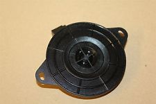
This is a part of the Bosch Contentious Injection System (CIS) otherwise referred to as K-jetronic (k-jet) systems. Found on UK 8v GTIs between 1984-1987, CIS was used in other models around the world as either K-Jet or KE-Jet. The 16v also used the K-Jet system however these were different to the 8v by way of having an ECU. The AAV was not present in the 16v setup, instead was replaced by the elecrtonically controlled Idle Stabilisation Valve (ISV).
It is mounted on a small bracket within the inside curvature of the inlet manifold.
Item 19 on the top picture:
Product information During the startup phase, the auxiliary air device provides additional air so that, together with the additionally supplied fuel, the greater friction of the cold engine can be overcome. An aperture in the auxiliary air device controls the amount of air that flows through. It is installed on the engine to absorb its heat. It is also electrically heated to track with the engine characteristic. The hotter the engine, the less additional air is provided. The auxiliary air device is therefore a functional component of the fuel injection system.
Benefits reliable start with cold engine
Bosch part numbers Bosch part number Replacement number 0 280 140 145 - - - - - F 026 T03 050 0 280 140 146 - - - - - F 026 T03 050 0 280 140 164 - - - - - F 026 T03 051 0 280 140 165 - - - - - F 026 T03 051
External numbers Vehicle make - - - - - - - - External number - - - - - - Bosch part number VW (Volkswagen) - - - - - 049 133 453 - - - - - - - - F 026 T03 050 VW (Volkswagen) - - - - - 049 133 453 E - - - - - - - F 026 T03 051
The standard speakers fitted from factory are as follows.
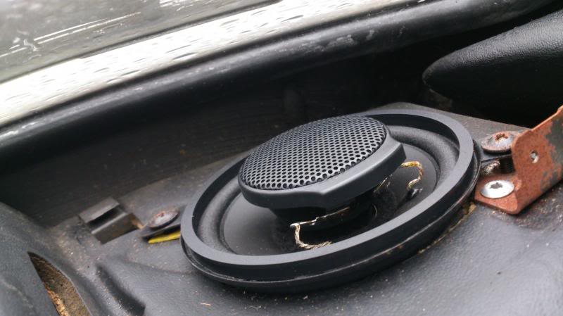
Dash: 3.5" (8cm) behind plastic grills.
Early cars and lower spec cars without door speakers came with a pair of 3.5" or 8cm dual cone speakers behind plastic grills.
Aftermarket 2 way upgrade:
For cars with Door speakers the dash speakers were replaced with component tweeters in a plastic shell so they occupy the same dimensions of the standard speakers.
If you ever have to remove the windscreen or the dash I recommend upgrading the speakers at that time as they're a real pig to do with both in situ.
Door: 5.25" (13cm) in pods within the door bins.
Some Golfs were luck enough to come with the VW 6 speaker "Active" system. This put a 5" speaker in the door and seperate tweeter in the dash as mentioned above. The door pods replaced the cubby comparments that came in 87 onward cars. Pre-87 the door bins din't have these cubbies.
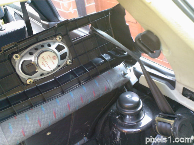
Rear: 6x4" oval speakers were fitted in the parcel shelf supports
Paper dual cone oval speakers were fitted in the rear. Fitted from underneath on 4 locating dowels on each of the parcel self supports. Due to the space hear upgrades are limited in terms of size, but there are many manufacturers that offer quality direct replacement items.
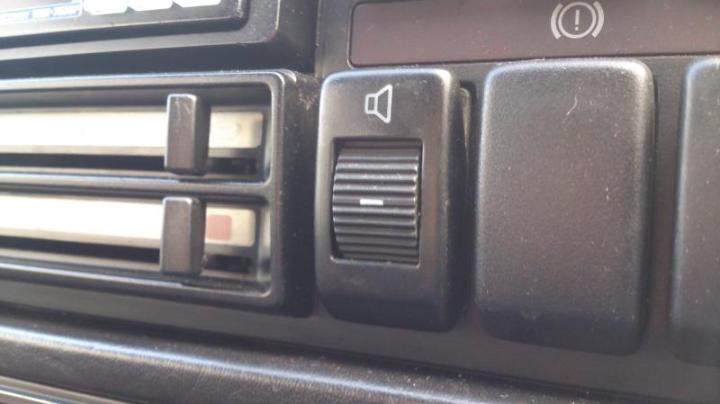
Fader: As the mind to late 80s was when In Car Entertainment began to take off as a 'thing' the car radios fitted in some of the early cars were very basic. As such they only had two speaker outputs for left and right. To combat this and to add the lucury of rear speakers some early cars were fitted with a fader switch.
Taking the left and right outputs from the car radio and splitting them to front and rear as well. Clever stuff! :thumbs: it wasn't long before car stereos had 4 outputs as standard making these switches redundant.
The alternator is a dynamo that generates an alternating current.
The role of the alternator is to charge up the battery while the engine is running. Car batteries deliver power to your headlights, stereo and a number of other electrical parts inside your car and it needs to be recharged.
Alternators are used as a battery charger, delivering new energy to the battery so that it has all it needs to deliver power to the car time and time again. Many believe that the car not starting is down to a fault with the car battery, when in actual fact it is the alternator to blame for not recharging the battery, allowing it to go flat.
The alternator is driven by a V belt off the main crank pulley. The belt also runs the water pump so should the belt snap you might think it's OK you could run without electrics, but this is not the case as you'll very quickly overheat.
The arrangement of the belts will be something like this. Depending on the configuration with or without Power Steering or Air con it may be slightly different.
Just an update on the National Club meet 17-19 July 2020.
Ok, not really sure what to say, it’s everywhere we look Covid19 and events being cancelled.
We are keeping up to date with government information and have been in touch with Curborough ; who’s line is at the moment that events are cancelled, however at the moment speaking with Curborough Club Secretary, neither of us can guarantee that the meet can go ahead, but we are in close contact with the secretary and he will advise as soon as he can and Club admins will come to a decision at the end of May, however this maybe taken out of our control at some point. This is heart breaking to have to think about the possibility of cancelling, but members safety is our up most priority.
If the meet is cancelled, refunds will be given or you can keep your ticket for the following year, once a decision has been reached.
We hope that you stay safe in this uncertain time.
Chris & Shelly
We hope your all keeping safe.
Just a quick update, Curborough have announced today, that events up until the end of Jun 20 are definitely cancelled. So we are just holding our breath at the moment to hear beyond this.